
Datasheet


Section 11 16-Bit Timer Pulse Unit (TPU)
R01UH0310EJ0500 Rev. 5.00 Page 701 of 1384
Sep 25, 2012
H8S/2426, H8S/2426R, H8S/2424 Group
Section 11 16-Bit Timer Pulse Unit (TPU)
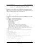
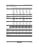
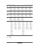
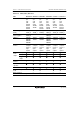
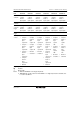
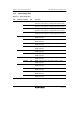
This LSI has two on-chip 16-bit timer pulse units (TPU: unit 0 and unit 1) which each comprises
six 16-bit timer channels, resulting in a total of 12 channels. The functions of unit 0 are listed in
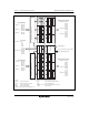
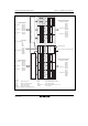
table 11.1, and the functions of unit 1 are listed in table 11.2. The block diagram of unit 0 is shown
in figure 11.1 and the block diagram of unit 1 is shown in figure 11.2.
The descriptions in this section refer to unit 0.
11.1 Features
• Maximum 32-pulse input/output (unit 0: 16, unit 1: 16, when the EXPE bit is 0 in single-chip
mode)
• Selection of 8 counter input clocks for each channel
• The following operations can be set for each channel:
⎯ Waveform output at compare match
⎯ Input capture function
⎯ Counter clear operation
⎯ Synchronous operations:
Multiple timer counters (TCNT) can be written to simultaneously.
Simultaneous clearing by compare match and input capture possible
Register simultaneous input/output possible by counter synchronous operation
⎯ Maximum of 15-phase PWM output possible by combination with synchronous operation
• Buffer operation settable for channels 0 (6) and 3 (9)
• Phase counting mode settable independently for each of channels 1 (7), 2 (8), 4 (10), and 5
(11)
• Cascaded operation
• Fast access via internal 16-bit bus
• 26 interrupt sources (per unit)
• Automatic transfer of register data
• Programmable pulse generator (PPG) output trigger can be generated (only by unit 0).
• A/D converter conversion start trigger can be generated.
• Module stop state can be set.
• Activation of the DMAC (only by unit 0) and DTC