
Datasheet


Section 10 I/O Ports
Page 658 of 1384 R01UH0310EJ0500 Rev. 5.00
Sep 25, 2012
H8S/2426, H8S/2426R, H8S/2424 Group
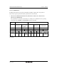
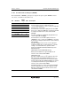
10.14.1 Port F Data Direction Register (PFDDR)
The individual bits of PFDDR specify input or output for the pins of port F. PFDDR cannot be
read; if it is, an undefined value will be read.
Bit Bit Name
Initial
Value R/W Description
7 PF7DDR 1/0
*
W
6 PF6DDR 0 W
5 PF5DDR 0 W
4 PF4DDR 0 W
3 PF3DDR 0 W
2 PF2DDR 0 W
1 PF1DDR 0 W
0 PF0DDR 0 W
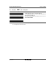
• Modes 1, 2, and 4 Modes 3 and 7 (EXPE = 1)
Pin PF7 functions as the φ output pin when the
corresponding PFDDR bit is set to 1, and as an input port
when the bit is cleared to 0.
Pin PF6 functions as the AS output pin when the ASOE
bit is set to 1. When the ASOE bit is cleared to 0, pin PF6
is an I/O port and its function can be switched with
PF6DDR.
Pins PF5 and PF4 are automatically designated as bus
control outputs (RD and HWR).
Pin PF3 functions as the LWR output pin when the
LWROE bit is set to 1. When the LWROE bit is cleared to
0, pin PF3 is an I/O port and its function can be switched
with PF3DDR.
Pins PF2 and PF1 function as bus control output pins
(LCAS and UCAS) when the appropriate bus controller
settings*
2
are made. Otherwise, operations differ
between the H8S/2426 and H8S/2426R Groups and
H8S/2424 Group.
[H8S/2426 Group and H8S/2426R Group]
When pins PF2 and PF1 are general I/O ports, the
function can be switched with PFDDR.
[H8S/2424 Group]
Pins PF2 and PF1 function as CS output pins when the
CS output enable bits (CS6E and CS5E) are set to 1,
and as input ports when the bits are cleared to 0. When
the CS output enable bits (CS6E and CS5E) are cleared
to 0 and pins PF2 and PF1 are general I/O ports, the
function can be switched with PFDDR.
The PF0 pin functions as a bus control input pin (WAIT)
when the appropriate bus controller settings are made.
Otherwise, PF0 is an I/O port and the function can be
switched with PF0DDR.