
Datasheet


Section 9 Data Transfer Controller (DTC)
R01UH0310EJ0500 Rev. 5.00 Page 481 of 1384
Sep 25, 2012
H8S/2426, H8S/2426R, H8S/2424 Group
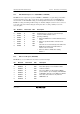
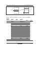
9.2.7 DTC Enable Registers A to I (DTCERA to DTCERI)
DTCER which is comprised of registers, DTCERA to DTCERI, is a register that specifies DTC
activation interrupt sources. The correspondence between interrupt sources and DTCE bits is
shown in table 9.2. For DTCE bit setting, use bit manipulation instructions such as BSET and
BCLR for reading and writing. If all interrupts are masked, multiple activation sources can be set
at one time (only at the initial setting) by writing data after executing a dummy read on the
relevant register.
Bit Bit Name Initial Value R/W Description
7
6
5
4
3
2
1
0
DTCE7
DTCE6
DTCE5
DTCE4
DTCE3
DTCE2
DTCE1
DTCE0
0
0
0
0
0
0
0
0
R/W
R/W
R/W
R/W
R/W
R/W
R/W
R/W
DTC Activation Enable
Setting this bit to 1 specifies a relevant interrupt
source to a DTC activation source.
[Clearing conditions]
• When the DISEL bit is 1 and the data transfer has
ended
• When the specified number of transfers have
ended
These bits are not automatically cleared when the
DISEL bit is 0 and the specified number of
transfers have not ended
• When 0 is written to DTCE after reading
DTCE = 1
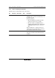
9.2.8 DTC Vector Register (DTVECR)
DTVECR sets a vector number for the software activation interrupt.
Bit Bit Name Initial Value R/W Description
7
6
5
4
3
2
1
0
DTVEC7
DTVEC6
DTVEC5
DTVEC4
DTVEC3
DTVEC2
DTVEC1
DTVEC0
0
0
0
0
0
0
0
0
R/W
R/W
R/W
R/W
R/W
R/W
R/W
R/W
DTC Software Activation Vectors 7 to 0
These bits specify a vector number for DTC
software activation.
The vector address is expressed as H'0400 +
(vector number × 2). For example, when DTVEC7
to DTVEC0 = H'10, the vector address is H'0420.
These bits can be written to only when the
SWDTE bit is 0.