
Datasheet


Section 9 Data Transfer Controller (DTC)
R01UH0310EJ0500 Rev. 5.00 Page 477 of 1384
Sep 25, 2012
H8S/2426, H8S/2426R, H8S/2424 Group
9.2 Register Descriptions
DTC has the following registers.
• DTC mode register A (MRA)
• DTC mode register B (MRB)
• DTC source address register (SAR)
• DTC destination address register (DAR)
• DTC transfer count register A (CRA)
• DTC transfer count register B (CRB)
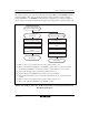
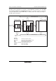
These six registers cannot be directly accessed from the CPU. When activated, the DTC reads a
set of register information that is stored in an on-chip RAM to the corresponding DTC registers
and transfers data. After the data transfer, it writes a set of updated register information back to the
RAM.
• DTC enable registers A to I (DTCERA to DTCERI)
• DTC vector register (DTVECR)
• DTC control register (DTCCR)
9.2.1 DTC Mode Register A (MRA)
MRA selects the DTC operating mode.
Bit Bit Name Initial Value R/W Description
7
6
SM1
SM0
Undefined
Undefined
⎯
⎯
Source Address Mode 1 and 0
These bits specify an SAR operation after a data
transfer.
0x: SAR is fixed
10: SAR is incremented after a transfer
(by +1 when Sz = 0; by +2 when Sz = 1)
11: SAR is decremented after a transfer
(by –1 when Sz = 0; by –2 when Sz = 1)