
Datasheet


Section 8 EXDMA Controller (EXDMAC)
R01UH0310EJ0500 Rev. 5.00 Page 471 of 1384
Sep 25, 2012
H8S/2426, H8S/2426R, H8S/2424 Group
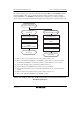
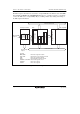
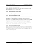
The transfer end interrupt can be cleared either by clearing the IRF bit to 0 in EDMDR within the
interrupt handling routine, or by re-setting the transfer counter and address registers and then
setting the EDA bit to 1 in EDMDR to perform transfer continuation processing. An example of
the procedure for clearing the transfer end interrupt and restarting transfer is shown in figure 8.46.
[1] Write set values to the registers (transfer counter, address registers, etc.).
[2] Write 1 to the EDA bit in EDMDR to restart EXDMA operation. When 1 is written to the EDA
bit, the IRF bit in EDMDR is automatically cleared to 0 and the interrupt source is cleared.
[3] The interrupt handling routine is ended with an RTE instruction, etc.
[4] Clear the IRF bit to 0 in EDMDR by first reading 1 from it, then writing 0.
[5] After the interrupt handling routine is ended with an RTE instruction, etc., interrupt masking is
cleared.
[6] Write set values to the registers (transfer counter, address registers, etc.).
[7] Write 1 to the EDA bit in EDMDR to restart EXDMA operation.
End of transfer restart
processing
Write 1 to EDA bit
Change register settings
End of interrupt handling
routine
Clear IRF bit to 0
Transfer restart after end
of interrupt handling routine
Transfer end interrupt
exception handling routine
Transfer continuation
processing
Change register settings
Write 1 to EDA bit
End of interrupt handling
routine
(RTE instruction execution)
End of transfer restart
processing
[1]
[4]
[5]
[6]
[7]
[2]
[3]
Figure 8.46 Example of Procedure for Restarting Transfer on Channel in which Transfer
End Interrupt Occurred