
Datasheet

Section 8 EXDMA Controller (EXDMAC)
Page 470 of 1384 R01UH0310EJ0500 Rev. 5.00
Sep 25, 2012
H8S/2426, H8S/2426R, H8S/2424 Group
8.5 Interrupt Sources
EXDMAC interrupt sources are a transfer end indicated by the transfer counter, and repeat area
overflow interrupts. Table 8.4 shows the interrupt sources and their priority order.
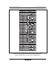
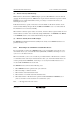
Table 8.4 Interrupt Sources and Priority Order
Interrupt Interrupt source Interrupt Priority
EXDMTEND2 Transfer end indicated by channel 2 transfer counter
Channel 2 source address repeat area overflow
Channel 2 destination address repeat area overflow
High
EXDMTEND3 Transfer end indicated by channel 3 transfer counter
Channel 3 source address repeat area overflow
Channel 3 destination address repeat area overflow
Low
Interrupt sources can be enabled or disabled by means of the EDIE bit in EDMDR for the relevant
channel, and can be sent to the interrupt controller independently. The relative priority order of the
channels is determined by the interrupt controller (see table 8.4).
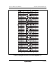
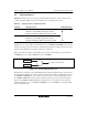
Figure 8.45 shows the transfer end interrupt logic. A transfer end interrupt is generated whenever
the EDIE bit is set to 1 while the IRF bit is set to 1 in EDMDR.
Transfer end interrupt
IRF bit
EDIE bit
Figure 8.45 Transfer End Interrupt Logic
Interrupt source settings are made individually with the interrupt enable bits in the registers for the
relevant channels. The transfer counter's transfer end interrupt is enabled or disabled by means of
the TCEIE bit in EDMDR, the source address register repeat area overflow interrupt by means of
the SARIE bit in EDACR, and the destination address register repeat area overflow interrupt by
means of the DARIE bit in EDACR. When an interrupt source occurs while the corresponding
interrupt enable bit is set to 1, the IRF bit in EDMDR is set to 1. The IRF bit is set by all interrupt
sources indiscriminately.