
Datasheet


Section 8 EXDMA Controller (EXDMAC)
Page 420 of 1384 R01UH0310EJ0500 Rev. 5.00
Sep 25, 2012
H8S/2426, H8S/2426R, H8S/2424 Group
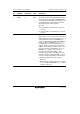
Bit Bit Name Initial Value R/W Description
7
6
DAT1
DAT0
0
0
R/W
R/W
Destination Address Update Mode
These bits specify incrementing/decrementing of
the transfer destination address (EDDAR). When
an external device with DACK is designated as the
transfer destination in single address mode, the
specification by these bits is ignored.
0x: Fixed
10: Incremented (+1 in byte transfer, +2 in word
transfer)
11: Decremented (–1 in byte transfer, –2 in word
transfer)
5 DARIE 0 R/W Destination Address Repeat Interrupt Enable
When this bit is set to 1, in the event of destination
address repeat area overflow the IRF bit is set to 1
and the EDA bit cleared to 0 in EDMDR, and
transfer is terminated. If the EDIE bit in EDMDR is
1 when the IRF bit in EDMDR is set to 1, an
interrupt request is sent to the CPU. When used
together with block transfer mode, a destination
address repeat interrupt is requested at the end of
a block-size transfer. If the EDA bit is set to 1 in
EDMDR for the channel on which transfer is
terminated by a destination address repeat
interrupt, transfer can be resumed from the state
in which it ended. If a destination address repeat
area has not been designated, this bit is ignored.
0: Destination address repeat interrupt is not
requested
1: When destination address repeat area overflow
occurs, the IRF bit in EDMDR is set to 1 and an
interrupt is requested