
Datasheet

Section 7 DMA Controller (DMAC)
Page 352 of 1384 R01UH0310EJ0500 Rev. 5.00
Sep 25, 2012
H8S/2426, H8S/2426R, H8S/2424 Group
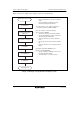
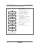
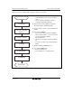
Figure 7.4 shows an example of the setting procedure for sequential mode.
Sequential mode setting
Set DMABCRH
Set transfer source
and transfer destination
addresses
Set number of transfers
Set DMACR
Read DMABCRL
Set DMABCRL
Sequential mode
[1]
[2]
[3]
[4]
[5]
[6]
[1] Set each bit in DMABCRH.
• Clear the FAE bit to 0 to select short address
mode.
• Specify enabling or disabling of internal
interrupt clearing with the DTA bit.
[2] Set the transfer source address and transfer
destination address in MAR and IOAR.
[3] Set the number of transfers in ETCR.
[4] Set each bit in DMACR.
• Set the transfer data size with the DTSZ bit.
• Specify whether MAR is to be incremented or
decremented with the DTID bit.
• Clear the RPE bit to 0 to select sequential
mode.
• Specify the transfer direction with the DTDIR
bit.
• Select the activation source with bits DTF3 to
DTF0.
[5] Read the DTE bit in DMABCRL as 0.
[6] Set each bit in DMABCRL.
• Specify enabling or disabling of transfer end
interrupts with the DTIE bit.
• Set the DTE bit to 1 to enable transfer.
Figure 7.4 Example of Sequential Mode Setting Procedure