
Datasheet

Section 6 Bus Controller (BSC)
R01UH0310EJ0500 Rev. 5.00 Page 307 of 1384
Sep 25, 2012
H8S/2426, H8S/2426R, H8S/2424 Group
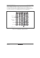
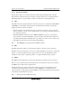
6.12.3 Transition Timing
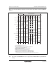
Figure 6.96 shows the timing for transition to the bus released state.
CPU
cycle
External bus released state
External space
access cycle
T
1
T
2
φ
A
ddress bus
HWR, LWR
BREQ
BACK
BREQO
High impedance
High impedance
High impedance
High impedance
High impedance
[1] [2] [3] [5][4]
[6] [7] [8]
[1] Low level of BREQ signal is sampled at rise of φ.
[2] Bus control signal returns to be high at end of external space access cycle.
At least one state from sampling of BREQ signal.
[3] BACK signal is driven low, releasing bus to external bus master.
[4] BREQ signal state is also sampled in external bus released state.
[5] High level of BREQ signal is sampled.
[6] BACK signal is driven high, ending external bus release cycle.
[7] When there is external access or refresh request of internal bus master during external
bus release while BREQOE bit is set to 1, BREQO signal goes low.
[8] Normally BREQO signal goes high 1.5 states after rising edge of BACK signal. If BREQO
signal is asserted because of CBR-refreshing request, it retains low until CBR-refresh cycle starts up.
Data bus
AS
RD
Note: The refresh control function is not supported by the 5-V version.
Figure 6.96 Bus Released State Transition Timing