
Datasheet


Section 6 Bus Controller (BSC)
R01UH0310EJ0500 Rev. 5.00 Page 299 of 1384
Sep 25, 2012
H8S/2426, H8S/2426R, H8S/2424 Group
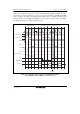
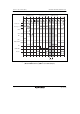
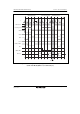
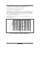
Table 6.12 shows whether there is an idle cycle insertion or not in the case of mixed accesses to
normal space and DRAM space/continuous synchronous DRAM space.
Table 6.12 Idle Cycles in Mixed Accesses to Normal Space and DRAM Continuous
Synchronous DRAM Space
Previous Access Next Access ICIS2 ICIS1 ICIS0 DRMI IDLC Idle cycle
⎯ 0 ⎯ ⎯ ⎯ Disabled
⎯ 1 ⎯ ⎯ 0 1 state inserted
Normal space read
(different area)
1 2 states inserted
⎯ 0 ⎯ ⎯ ⎯ Disabled
⎯ 1 ⎯ ⎯ 0 1 state inserted
DRAM*
1
/continuous
synchronous DRAM*
2
space read
1 2 states inserted
⎯ ⎯ 0 ⎯ ⎯ Disabled
⎯ ⎯ 1 ⎯ 0 1 state inserted
Normal space write
1 2 states inserted
⎯ ⎯ 0 ⎯ ⎯ Disabled
⎯ ⎯ 1 ⎯ 0 1 state inserted
Normal space read
DRAM*
1
/continuous
synchronous DRAM*
2
space write
1 2 states inserted
⎯ 0 ⎯ ⎯ ⎯ Disabled
⎯ 1 ⎯ 0 ⎯ Disabled
1 0 1 state inserted
Normal space read
1 2 states inserted
⎯ 0 ⎯ ⎯ ⎯ Disabled
⎯ 1 ⎯ 0 ⎯ Disabled
1 0 1 state inserted
DRAM*
1
/continuous
synchronous DRAM*
2
space read
1 2 states inserted
⎯ ⎯ 0 ⎯ ⎯ Disabled
⎯ ⎯ 1 0 ⎯ Disabled
1 0 1 state inserted
Normal space write
1 2 states inserted
⎯ ⎯ 0 ⎯ ⎯ Disabled
⎯ ⎯ 1 0 ⎯ Disabled
1 0 1 state inserted
DRAM*
1
/continuous
synchronous
DRAM*
2
space read
DRAM*
1
/continuous
synchronous DRAM*
2
space write
1 2 states inserted