
Datasheet


Section 6 Bus Controller (BSC)
Page 286 of 1384 R01UH0310EJ0500 Rev. 5.00
Sep 25, 2012
H8S/2426, H8S/2426R, H8S/2424 Group
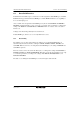
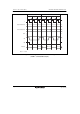
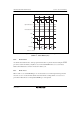
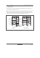
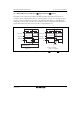
(3) Read after Write
If an external read occurs after an external write while the ICIS2 bit is set to 1 in BCR, an idle
cycle is inserted at the start of the read cycle.
Figure 6.79 shows an example of the operation in this case. In this example, bus cycle A is a CPU
write cycle and bus cycle B is a read cycle from an external device. In (a), an idle cycle is not
inserted, and a collision occurs in bus cycle B between the CPU write data and read data from an
external device. In (b), an idle cycle is inserted, and a data collision is prevented.
T
1
A
ddress bus
φ
RD
Bus cycle A
Data bus
T
2
T
3
T
1
T
2
Bus cycle B
Long output floating time
Data collision
(a) No idle cycle insertion
(ICIS2 = 0)
T
1
Address bus
φ
RD
Bus cycle A
Data bus
T
2
T
3
T
1
Bus cycle B
(b) Idle cycle insertion
(ICIS2 = 1, initial value)
T
2
HWR
HWR, LWR
CS (area A)
CS (area B)
CS (area A)
CS (area B)
Idle cycle
T
i
Figure 6.79 Example of Idle Cycle Operation (Read after Write)