
Datasheet


Section 6 Bus Controller (BSC)
R01UH0310EJ0500 Rev. 5.00 Page 273 of 1384
Sep 25, 2012
H8S/2426, H8S/2426R, H8S/2424 Group
T
Rp
SDRAM
φ
Precharge-sel
Address bus
T
Rr
CAS
Software standby
T
Rc2
WE
CKE
RAS
NOPSELF
PALL
φ
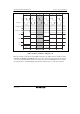
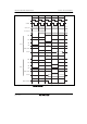
Figure 6.69 Self-Refresh Timing
(TPC1 = 1, TPC0 = 0, RCW1 = 0, RCW0 = 0, RLW1 = 0, RLW0 = 0)
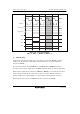
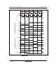
In some synchronous DRAMs provided with a self-refresh mode, the interval between clearing
self-refreshing and the next command is specified. A setting can be made in bits TPCS2 to TPCS0
in REFCR to make the precharge time after self-refreshing from 1 to 7 states longer than the
normal precharge time. In this case, too, normal precharging is performed according to the setting
of bits TPC1 and TPC0 in DRACCR, and therefore a setting should be made to give the optimum
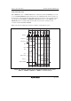
post-self-refresh precharge time, including this time. Figure 6.70 shows an example of the timing
when the precharge time after self-refreshing is extended by 2 states.