
Datasheet


Section 6 Bus Controller (BSC)
Page 256 of 1384 R01UH0310EJ0500 Rev. 5.00
Sep 25, 2012
H8S/2426, H8S/2426R, H8S/2424 Group
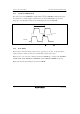
6.8.7 CAS Latency Control
CAS latency is controlled by settings of the W22 to W20 bits of WTCRB. Set the CAS latency
count, as shown in table 6.11, by the setting of synchronous DRAM. Depending on the setting, the
CAS latency control cycle (T
c1
) is inserted. WTCRB can be set regardless of the setting of the
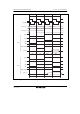
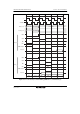
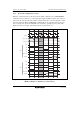
AST2 bit of ASTCR. Figure 6.57 shows the CAS latency control timing when synchronous
DRAM of CAS latency 3 is connected.
The initial value of W22 to W20 is H'7. Set the register according to the CAS latency of
synchronous DRAM to be connected.
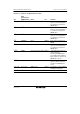
Table 6.11 Setting CAS Latency
W22 W21 W20 Description
CAS Latency Control
Cycle Inserted
0 0 0 Connect synchronous DRAM of CAS
latency 1
0 state
1 Connect synchronous DRAM of CAS
latency 2
1 state
1 0 Connect synchronous DRAM of CAS
latency 3
2 states
1 Connect synchronous DRAM of CAS
latency 4
3 states
1 0 0 Reserved (must not be used) ⎯
1 Reserved (must not be used) ⎯
1 0 Reserved (must not be used) ⎯
1 Reserved (must not be used) ⎯