
Datasheet


Section 6 Bus Controller (BSC)
Page 252 of 1384 R01UH0310EJ0500 Rev. 5.00
Sep 25, 2012
H8S/2426, H8S/2426R, H8S/2424 Group
6.8.3 Data Bus
If the ABW2 bit in ABWCR corresponding to an area designated as continuous synchronous
DRAM space is set to 1, areas 2 to 5 are designated as 8-bit continuous synchronous DRAM
space; if the bit is cleared to 0, the areas are designated as 16-bit continuous synchronous DRAM
space. In 16-bit continuous synchronous DRAM space, ×16-bit configuration synchronous DRAM
can be connected directly.
In 8-bit continuous synchronous DRAM space the upper half of the data bus, D15 to D8, is
enabled, while in 16-bit continuous synchronous DRAM space both the upper and lower halves of
the data bus, D15 to D0, are enabled.
Access sizes and data alignment are the same as for the basic bus interface: see section 6.5.1, Data
Size and Data Alignment.
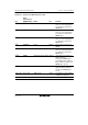
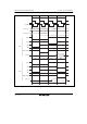
6.8.4 Pins Used for Synchronous DRAM Interface
Table 6.10 shows pins used for the synchronous DRAM interface and their functions.
Set the OEE bit in DRAMCR to 1 when the CKE signal is output.