
Datasheet


Section 6 Bus Controller (BSC)
R01UH0310EJ0500 Rev. 5.00 Page 205 of 1384
Sep 25, 2012
H8S/2426, H8S/2426R, H8S/2424 Group
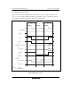
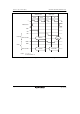
By program wait
T
1
Address bus
φ
AS
RD
Data bus
Read data
Read
HWR, LWR
Write data
Write
WAIT
Data bus
T
2
T
w
T
w
T
w
T
3
By WAIT pin
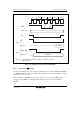
Notes: 1. Downward arrows indicate the timing of WAIT pin sampling.
2. When RDNn = 0
Figure 6.18 Example of Wait State Insertion Timing
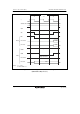
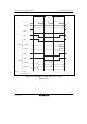
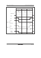
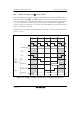
6.5.5 Read Strobe (RD) Timing
The read strobe (RD) timing can be changed for individual areas by setting bits RDN7 to RDN0 to
1 in RDNCR. Figure 6.19 shows an example of the timing when the read strobe timing is changed
in basic bus 3-state access space.
When the DMAC or EXDMAC is used in single address mode, note that if the RD timing is
changed by setting RDNn to 1, the RD timing will change relative to the rise of DACK or
EDACK.