
Datasheet


Section 6 Bus Controller (BSC)
Page 204 of 1384 R01UH0310EJ0500 Rev. 5.00
Sep 25, 2012
H8S/2426, H8S/2426R, H8S/2424 Group
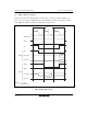
6.5.4 Wait Control
When accessing external space, this LSI can extend the bus cycle by inserting one or more wait
states (T
w
). There are two ways of inserting wait states: program wait insertion and pin wait
insertion using the WAIT pin.
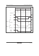
(1) Program Wait Insertion
From 0 to 7 wait states can be inserted automatically between the T
2
state and T
3
state on an
individual area basis in 3-state access space, according to the settings in WTCRA and WTCRB.
(2) Pin Wait Insertion
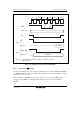
Setting the WAITE bit to 1 in BCR enables wait input by means of the WAIT pin. When external
space is accessed in this state, a program wait is first inserted in accordance with the settings in
WTCRA and WTCRB. If the WAIT pin is low at the falling edge of φ in the last T
2
or T
w
state,
another T
w
state is inserted. If the WAIT pin is held low, T
w
states are inserted until it goes high.
This is useful when inserting seven or more T
w
states, or when changing the number of T
w
states to
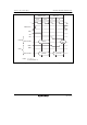
be inserted for different external devices. The WAITE bit setting applies to all areas. Figure 6.18
shows an example of wait state insertion timing.
The settings after a reset are: 3-state access, insertion of 7 program wait states, and WAIT input
disabled.