
Datasheet


Section 6 Bus Controller (BSC)
Page 188 of 1384 R01UH0310EJ0500 Rev. 5.00
Sep 25, 2012
H8S/2426, H8S/2426R, H8S/2424 Group
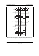
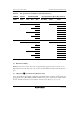
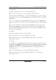
Table 6.2 Bus Specifications for Each Area (Basic Bus Interface)
ABWCR ASTCR WTCRA, WTCRB Bus Specifications (Basic Bus Interface)
ABWn ASTn Wn2 Wn1 Wn0 Bus Width
Access
States
Program Wait
States
0 0 ⎯ ⎯ ⎯ 16 2 0
1 0 0 0 3 0
1 1
1 0 2
1 3
1 0 0 4
1 5
1 0 6
1 7
1 0 ⎯ ⎯ ⎯ 8 2 0
1 0 0 0 3 0
1 1
1 0 2
1 3
1 0 0 4
1 5
1 0 6
1 7
(n = 0 to 7)
(4) Read Strobe Timing
RDNCR can be used to select either of two negation timings (at the end of the read cycle or one
half-state before the end of the read cycle) for the read strobe (RD) used in the basic bus interface
space.
(5) Chip Select (CS) Assertion Period Extension States
Some external I/O devices require a setup time and hold time between address and CS signals and
strobe signals such as RD, HWR, and LWR. CSACR can be used to insert states in which only the
CS, AS, and address signals are asserted before and after a basic bus space access cycle.