
Datasheet


Section 6 Bus Controller (BSC)
Page 184 of 1384 R01UH0310EJ0500 Rev. 5.00
Sep 25, 2012
H8S/2426, H8S/2426R, H8S/2424 Group
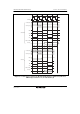
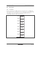
Bit Bit Name Initial Value R/W Description
5
4
RLW1
RLW0
0
0
R/W
R/W
Refresh Cycle Wait Control
These bits select the number of wait states to be
inserted in a DRAM interface CAS-before-RAS
refresh cycle/synchronous DRAM interface auto-
refresh cycle. This setting applies to all areas
designated as DRAM/continuous synchronous
DRAM space.
00: No wait state inserted
01: 1 wait state inserted
10: 2 wait states inserted
11: 3 wait states inserted
3 SLFRF 0 R/W Self-Refresh Enable
If this bit is set to 1, DRAM/synchronous DRAM
self-refresh mode is selected when a transition is
made to the software standby state. This bit is
valid when the RFSHE bit is set to 1, enabling
refresh operations. It is cleared after recovery from
software standby mode.
0: Self-refreshing is disabled
1: Self-refreshing is enabled
2
1
0
TPCS2
TPCS1
TPCS0
0
0
0
R/W
R/W
R/W
Self-Refresh Precharge Cycle Control
These bits select the number of states in the
precharge cycle immediately after self-refreshing.
The number of states in the precharge cycle
immediately after self-refreshing are added to the
number of states set by bits TPC1 and TPC0 in
DRACCR.
000: [TPC set value] states
001: [TPC set value + 1] states
010: [TPC set value + 2] states
011: [TPC set value + 3] states
100: [TPC set value + 4] states
101: [TPC set value + 5] states
110: [TPC set value + 6] states
111: [TPC set value + 7] states