
Datasheet

Section 6 Bus Controller (BSC)
R01UH0310EJ0500 Rev. 5.00 Page 173 of 1384
Sep 25, 2012
H8S/2426, H8S/2426R, H8S/2424 Group
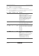
Bit Bit Name Initial Value R/W Description
10
9
8
RMTS2
RMTS1
RMTS0
0
0
0
R/W
R/W
R/W
DRAM/Continuous Synchronous DRAM Space
Select
These bits designate DRAM/continuous
synchronous DRAM space for areas 2 to 5.
When continuous DRAM space is set, it is
possible to connect large-capacity DRAM
exceeding 2 Mbytes per area. In this case, the
RAS signal is output from the CS2 pin.
When continuous synchronous DRAM space is
set, it is possible to connect large-capacity
synchronous DRAM exceeding 2 Mbytes per area.
In this case, the RAS, CAS, and WE signals are
output from CS2, CS3, and CS4 pins,
respectively. When synchronous DRAM mode is
set, the mode registers of the synchronous DRAM
can be set.
000: Normal space
001: Normal space in areas 3 to 5
DRAM space in area 2
010: Normal space in areas 4 and 5
DRAM space in areas 2 and 3
011: DRAM space in areas 2 to 5
100: Continuous synchronous DRAM space
(setting possible only in H8S/2426R Group)
101: Synchronous DRAM mode setting (setting
possible only in H8S/2426R Group)
110: Setting prohibited
111: Continuous DRAM space in areas 2 to 5
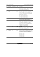
7 BE 0 R/W Burst Access Enable
Selects enabling or disabling of burst access to
areas designated as DRAM/continuous
synchronous DRAM space. DRAM/continuous
synchronous DRAM space burst access is
performed in fast page mode. When using EDO
page mode DRAM, the OE signal must be
connected.
0: Full access
1: Access in fast page mode