
Datasheet
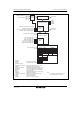


Section 6 Bus Controller (BSC)
R01UH0310EJ0500 Rev. 5.00 Page 153 of 1384
Sep 25, 2012
H8S/2426, H8S/2426R, H8S/2424 Group
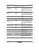
Name Symbol I/O Function
Chip select 4/
row address strobe 4*
1
/
write enable*
2
CS4/
RAS4*
1
/
WE*
2
Output Strobe signal indicating that area 4 is
selected, DRAM row address strobe signal
when area 4 is DRAM space, or write
enable signal of the synchronous DRAM
when the synchronous DRAM interface is
selected.
Chip select 5/
row address strobe 5*
1
/
SDRAMφ*
2
CS5/
RAS5*
1
/
SDRAMφ*
2
Output Strobe signal indicating that area 5 is
selected, DRAM row address strobe signal
when area 5 is DRAM space, or dedicated
clock signal for the synchronous DRAM
when the synchronous DRAM interface is
selected.
Chip select 6 CS6 Output Strobe signal indicating that area 6 is
selected.
Chip select 7 CS7 Output Strobe signal indicating that area 7 is
selected.
Upper column address
strobe*
1
/
upper data mask enable*
2
UCAS*
1
/
DQMU*
2
Output 16-bit DRAM space upper column address
strobe signal, 8-bit DRAM space column
address strobe signal, upper data mask
signal of 16-bit synchronous DRAM space,
or data mask signal of 8-bit synchronous
DRAM space.
Lower column address strobe/
lower data mask enable
LCAS*
1
/
DQML*
2
Output 16-bit DRAM space lower column address
strobe signal or lower data mask signal for
the 16-bit synchronous DRAM space.
Output enable/clock enable OE*
1
/
CKE*
2
Output Output enable signal for the DRAM space
or clock enable signal for the synchronous
DRAM space.
Wait WAIT Input Wait request signal when accessing
external address space.
Bus request BREQ Input Request signal for release of bus to
external bus master.
Bus request acknowledge BACK Output Acknowledge signal indicating that bus has
been released to external bus master.
Bus request output BREQO Output External bus request signal used when
internal bus master accesses external
address space when external bus is
released.