
Datasheet


Section 5 Interrupt Controller
Page 128 of 1384 R01UH0310EJ0500 Rev. 5.00
Sep 25, 2012
H8S/2426, H8S/2426R, H8S/2424 Group
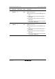
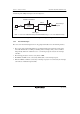
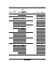
A block diagram of IRQn interrupts is shown in figure 5.2.
IRQn interrupt
request
IRQnE
IRQnF
S
R
Q
Clear signal
Edge/
level detection
circuit
IRQnSCA, IRQnSCB
IRQn
input
Note: n = 0 to 15 for H8S/2426 Group and H8S/2426R Group, n = 0 to 7 for H8S/2424 Group
Figure 5.2 Block Diagram of IRQ Interrupts
5.4.2 Internal Interrupts
The sources for internal interrupts from on-chip peripheral modules have the following features:
• For each on-chip peripheral module there are flags that indicate the interrupt request status,
and enable bits that select enabling or disabling of these interrupts. They can be controlled
independently. When the enable bit is set to 1, an interrupt request is issued to the interrupt
controller.
• The interrupt priority level can be set by means of IPR.
• The DMAC and DTC can be activated by a TPU, SCI, or other interrupt request.
• When the DMAC or DTC is activated by an interrupt request, it is not affected by the interrupt
control mode or CPU interrupt mask bit.