
Datasheet


Section 5 Interrupt Controller
R01UH0310EJ0500 Rev. 5.00 Page 111 of 1384
Sep 25, 2012
H8S/2426, H8S/2426R, H8S/2424 Group
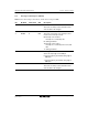
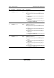
5.3.1 Interrupt Control Register (INTCR)
INTCR selects the interrupt control mode, and the detected edge for NMI.
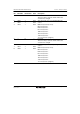
Bit Bit Name Initial Value R/W Description
7, 6 ⎯ All 0 ⎯ Reserved
These bits are always read as 0 and the initial
value should not be changed.
5
4
INTM1
INTM0
0
0
R/W
R/W
Interrupt Control Select Mode 1 and 0
These bits select either of two interrupt control
modes for the interrupt controller.
00: Interrupt control mode 0
Interrupts are controlled by I bit.
01: Setting prohibited.
10: Interrupt control mode 2
Interrupts are controlled by bits I2 to I0, and
IPR.
11: Setting prohibited.
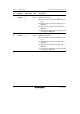
3 NMIEG 0 R/W NMI Edge Select
Selects the input edge for the NMI pin.
0: Interrupt request generated at falling edge of
NMI input
1: Interrupt request generated at rising edge of
NMI input
2 to 0 ⎯ All 0 ⎯ Reserved
These bits are always read as 0 and the initial
value should not be changed.