
Datasheet


Section 25 Electrical Characteristics
R01UH0310EJ0500 Rev. 5.00 Page 1249 of 1384
Sep 25, 2012
H8S/2426, H8S/2426R, H8S/2424 Group
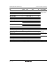
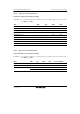
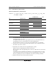
25.3.2 Control Signal Timing
The control signal timings are shown below.
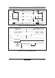
φ
RES
t
RESS
t
RESS
t
RESW
Figure 25.6 Reset Input Timing
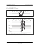
φ
NMI
IRQi
(i = 0 to 15)*
IRQ
(edge input)
Note: * SSIER setting is necessary to clear software standby mode.
t
NMIS
t
NMIH
t
IRQS
t
IRQS
t
IRQH
t
NMIW
t
IRQW
IRQ
(level input)
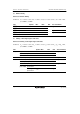
Figure 25.7 Interrupt Input Timing