
Datasheet


Section 25 Electrical Characteristics
R01UH0310EJ0500 Rev. 5.00 Page 1219 of 1384
Sep 25, 2012
H8S/2426, H8S/2426R, H8S/2424 Group
3. The values are for V
RAM
≤ V
CC
< 3.0 V, V
IH
min = V
CC
× 0.9, and V
IL
max = 0.3 V.
4. I
CC
depends on V
CC
and f as follows:
I
CC
max = 5.2 (mA) + 1.66 (mA/(MHz)) × f (normal operation)
I
CC
max = 2.6 (mA) + 1.28 (mA/(MHz)) × f (sleep mode)
5. Applied when RES is low at power-on.
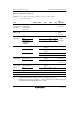
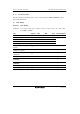
Table 25.4 Permissible Output Currents
Conditions: V
CC
= 3.0 V to 3.6 V, AV
CC
= 3.0 V to 3.6 V, V
ref
= 3.0 V to AV
CC
,
V
SS
= AV
SS
= 0 V*
Item Symbol Min. Typ. Max. Unit
All output pins
except the I
2
C pins
I
OL
⎯ ⎯ 4.0 mA Permissible output low
current (per pin)
I
2
C output pins I
OL
⎯ ⎯ 8.0 mA
Permissible output low
current (total)
Total of all output
pins
ΣI
OL
⎯ ⎯ 80 mA
Permissible output high
current (per pin)
All output pins −I
OH
⎯ ⎯ 2.0 mA
Permissible output high
current (total)
Total of all output
pins
Σ−I
OH
⎯ ⎯ 40 mA
Caution: To protect the LSI's reliability, do not exceed the output current values in table 25.4.
Note: * When the A/D and D/A converters are not used, do not leave the AV
CC
, V
ref
, and AV
SS
pins open. Connect the AV
CC
and V
ref
pins to V
CC
, and the AV
SS
pin to V
SS
.