
Datasheet


Section 23 Power-Down Modes
Page 1154 of 1384 R01UH0310EJ0500 Rev. 5.00
Sep 25, 2012
H8S/2426, H8S/2426R, H8S/2424 Group
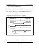
(3) Setting Oscillation Stabilization Time after Clearing Software Standby Mode
Bits STS3 to STS0 in SBYCR should be set as described below.
• Using a Crystal Resonator:
Set bits STS3 to STS0 so that the standby time is more than the oscillation stabilization time.
Table 23.2 shows the standby times for operating frequencies and settings of bits STS3 to
STS0.
• Using an External Clock:
A PLL circuit stabilization time is necessary. See table 23.2 to set the wait time.
Table 23.2 Oscillation Stabilization Time Settings
φ* [MHz]
STS3 STS2 STS1 STS0
Standby
Time
33 25 20 13 10 8 Unit
0 0 0 0 Reserved ⎯ ⎯ ⎯ ⎯ ⎯ ⎯ µs
1 Reserved ⎯ ⎯ ⎯ ⎯ ⎯ ⎯
1 0 Reserved ⎯ ⎯ ⎯ ⎯ ⎯ ⎯
1 Reserved ⎯ ⎯ ⎯ ⎯ ⎯ ⎯
1 0 0 Reserved ⎯ ⎯ ⎯ ⎯ ⎯ ⎯
1 64 1.9 2.6 3.2 4.9 6.4 8.0
1 0 512 15.5 20.5 25.6 39.4 51.2 64.0
1 1024 31.0 41.0 51.2 78.8 102.4 128.0
1 0 0 0 2048 62.1 81.9 102.4 157.5 204.8 256.0
1 4096 0.12 0.16 0.20 0.32 0.41 0.51 ms
1 0 16384 0.50 0.66 0.82 1.26 1.64 2.05
1 32765 0.99 1.31 1.64 2.52 3.28 4.10
1 0 0 65536 1.99 2.62 3.28 5.04 6.55 8.19
1 131072 3.97 5.24 6.55 10.08 13.11 16.38
1 0 262144 7.94 10.49 13.11 20.16 26.21 32.77
1 524288 15.89 20.97 26.21 40.33 52.43 65.54
Note: * φ is the frequency divider output.