
Datasheet


Section 23 Power-Down Modes
R01UH0310EJ0500 Rev. 5.00 Page 1153 of 1384
Sep 25, 2012
H8S/2426, H8S/2426R, H8S/2424 Group
23.2.3 Software Standby Mode
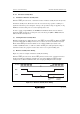
(1) Transition to Software Standby Mode
If a SLEEP instruction is executed when the SSBY bit in SBYCR is set to 1, software standby
mode is entered. In this mode, the CPU, on-chip peripheral functions, and oscillator all stop.
However, the contents of the CPU’s internal registers, RAM data, and the states of on-chip
peripheral functions other than the SCI, IIC, and SSU, and the states of I/O ports, are retained.
Whether the address bus and bus control signals are placed in the high-impedance state or retain
the output state can be specified by the OPE bit in SBYCR.
In this mode the oscillator stops, and therefore power dissipation is significantly reduced.
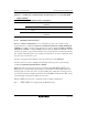
(2) Clearing Software Standby Mode
Software standby mode is cleared by an external interrupt (NMI pin, or pins IRQ0 to IRQ15*), or
by means of the RES pin or STBY pin. Setting the SSI bit in SSIER to 1 enables IRQ0 to IRQ15*
to be used as software standby mode clearing sources.
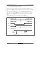
• Clearing with an Interrupt:
When an NMI or IRQ0 to IRQ15* interrupt request signal is input, clock oscillation starts, and
stable clocks are supplied to the entire LSI after the elapse of the time set in bits STS3 to STS0
in SBYCR. Then, software standby mode is cleared, and interrupt exception handling is
started.
When clearing software standby mode with an IRQ0 to IRQ15* interrupt, set the
corresponding enable bit to 1 and ensure that no interrupt with a higher priority than interrupts
IRQ0 to IRQ15* is generated. Software standby mode cannot be cleared if the interrupt has
been masked on the CPU side or has been designated as a DTC activation source.
Note: * IRQ8 to IRQ15 are not supported by the H8S/2424 group.
• Clearing with the RES Pin:
When the RES pin is driven low, clock oscillation is started. At the same time as clock
oscillation starts, clocks are supplied to the entire LSI. Note that the RES pin must be held low
until clock oscillation stabilizes. When the RES pin goes high, the CPU begins reset exception
handling.
• Clearing with the STBY Pin:
When the STBY pin is driven low, a transition is made to hardware standby mode.