
Datasheet


Section 23 Power-Down Modes
R01UH0310EJ0500 Rev. 5.00 Page 1151 of 1384
Sep 25, 2012
H8S/2426, H8S/2426R, H8S/2424 Group
23.2 Operation
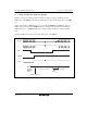
23.2.1 Clock Division Mode
When bits STC1 and STC0 in PLLCR are set to 11, a transition is made to clock division mode,
and the system clock frequency is divided with respect to the oscillator frequency. Clock division
mode is cancelled by clearing bits STC1 and STC0 to a value other than 11. The timings of
transition and clearing depend on the STCS bit setting in SCKCR. For the operation at transition
and clearing, see section 22.3, System-Clock PLL Circuit and Divider.
If a SLEEP instruction is executed while the SSBY bit in SBYCR is cleared to 0, the chip enters
sleep mode. When sleep mode is cleared by an interrupt, clock division mode is restored.
If a SLEEP instruction is executed while the SSBY bit in SBYCR is set to 1, the chip enters
software standby mode. When software standby mode is cleared by an external or internal
interrupt, clock division mode is restored.
When the RES pin is driven low, the reset state is entered and clock division mode is cleared. The
same applies to a reset caused by watchdog timer overflow.
When the STBY pin is driven low, a transition is made to hardware standby mode.