
Datasheet


Section 23 Power-Down Modes
Page 1146 of 1384 R01UH0310EJ0500 Rev. 5.00
Sep 25, 2012
H8S/2426, H8S/2426R, H8S/2424 Group
Bit Bit Name Initial Value R/W Description
5 ⎯ 0 ⎯ Reserved
This bit is always read as 0. The initial value
should not be changed.
4 ⎯ 0 ⎯ Reserved
This bit is always read as 0. The write value
should always be 0.
3
2
1
0
STS3
STS2
STS1
STS0
1
1
1
1
R/W
R/W
R/W
R/W
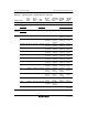
Standby Timer Select 3 to 0
These bits select the time the MCU waits for the
clock to stabilize when software standby mode is
cleared by an external interrupt. With crystal
oscillation, see table 23.2 and make a selection
according to the operating frequency so that the
standby time is at least the oscillation stabilization
time. With an external clock, a PLL circuit
stabilization time is necessary. See table 23.2 to
set the standby time. When DRAM is used and
self-refreshing in the software standby state is
selected, note that the DRAM’s tRAS (self-refresh
RAS pulse width) specification must be satisfied.
0000: Setting prohibited
0001: Setting prohibited
0010: Setting prohibited
0011: Setting prohibited
0100: Setting prohibited
0101: Standby time = 64 states
0110: Standby time = 512 states
0111: Standby time = 1024 states
1000: Standby time = 2048 states
1001: Standby time = 4096 states
1010: Standby time = 16384 states
1011: Standby time = 32768 states
1100: Standby time = 65536 states
1101: Standby time = 131072 states
1110: Standby time = 262144 states
1111: Standby time = 524288 states
Note: * Not included in the 5-V version.