
Datasheet


Section 23 Power-Down Modes
R01UH0310EJ0500 Rev. 5.00 Page 1145 of 1384
Sep 25, 2012
H8S/2426, H8S/2426R, H8S/2424 Group
23.1 Register Descriptions
The registers relating to the power-down mode are shown below. For details on the PLL control
register (PLLCR), see section 22.1.2, PLL Control Register (PLLCR).
• PLL control register (PLLCR)
• Standby control register (SBYCR)
• Module stop control register H (MSTPCRH)
• Module stop control register L (MSTPCRL)
• Extension module stop control register H (EXMSTPCRH)
• Extension module stop control register L (EXMSTPCRL)
• RAM module stop control register H (RMMSTPCRH)
• RAM module stop control register L (RMMSTPCRL)
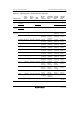
23.1.1 Standby Control Register (SBYCR)
SBYCR performs software standby mode control.
Bit Bit Name Initial Value R/W Description
7 SSBY 0 R/W
Software Standby
This bit specifies the transition mode after
executing the SLEEP instruction
0: Shifts to sleep mode after the SLEEP
instruction is executed
1: Shifts to software standby mode after the
SLEEP instruction is executed
This bit does not change from 1 when clearing the
software standby mode by using external
interrupts and shifting to normal operation. This bit
should be written 0 when clearing.
6 OPE 1 R/W
Output Port Enable
Specifies whether the output of the address bus
and bus control signals (CS0 to CS7, AS, RD,
HWR, LWR, UCAS*, LCAS*) is retained or set to
the high-impedance state in software standby
mode.
0: In software standby mode, address bus and bus
control signals are high-impedance
1: In software standby mode, address bus and bus
control signals retain output state