
Datasheet


Section 23 Power-Down Modes
Page 1144 of 1384 R01UH0310EJ0500 Rev. 5.00
Sep 25, 2012
H8S/2426, H8S/2426R, H8S/2424 Group
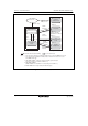
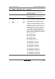
Program-halted stateProgram execution state
High-speed mode
(Internal clock is PLL
circuit output clock)
Reset state
STBY pin = low
STBY pin = high
RES pin = low
SSBY = 0
MSTPCR =
H'FFFF (H'FFFE),
EXMSTPCR = H'FFFF,
SSBY = 0
SSBY = 1
STC1,
STC0 = 11
RES pin = high
STC1,
STC0 ≠ 11
SLEEP
instruction
Interrupt
*1
: Transition after exception handling : Power- down mode
SLEEP
instruction
Any interrupt
SLEEP
instruction
External
interrupt
*2
Notes: • From any state, a transition to hardware standby mode occurs when STBY is driven low.
• From any state except hardware standby mode, a transition to the reset state occurs
when RES is driven low.
1. NMI, IRQ0 to IRQ15*
3
, 8-bit timer interrupts, watchdog timer interrupts.
(8-bit timer interrupts are valid when MSTP0 = 0.)
2. NMI, IRQ0 to IRQ15*
3
(IRQ0 to IRQ15*
3
are valid when the corresponding bit in SSIER is 1.)
3. IRQ8 to IRQ15 are not supported by the H8S/2424 group.
Hardware
standby mode
Sleep mode
All
module-clocks-stop
mode
Software
standby mode
Clock division
mode
Figure 23.1 Mode Transitions