
Datasheet


Section 22 Clock Pulse Generator
R01UH0310EJ0500 Rev. 5.00 Page 1139 of 1384
Sep 25, 2012
H8S/2426, H8S/2426R, H8S/2424 Group
22.4 Usage Notes
22.4.1 Notes on Clock Pulse Generator
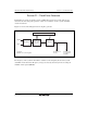
1. The following points should be noted since the frequency of φ changes according to the
settings of PLLCR.
Select a clock division ratio that is within the operation guaranteed range of clock cycle time
tcyc shown in the AC timing of the Electrical Characteristics. In other words, φ must be set to
a value between 8 MHz (minimum) and 33 MHz (maximum). The setting of φ must not be less
than 8 MHz or greater than 33 MHz.
2. All the on-chip peripheral modules operate on the φ. Therefore, note that the time processing
of modules such as a timer and SCI differ before and after changing the clock division ratio. In
addition, wait time for clearing software standby mode differs by changing the clock division
ratio. See the description, Setting Oscillation Stabilization Time after Clearing Software
Standby Mode in section 23.2.3, Software Standby Mode, for details.
3. Note that the frequency of φ will be changed when setting PLLCR while executing the external
bus cycle with the write-data-buffer function.
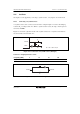
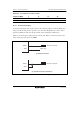
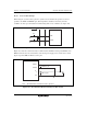
22.4.2 Notes on Resonator
Since various characteristics related to the resonator are closely linked to the user's board design,
thorough evaluation is necessary on the user's part, using the resonator connection examples
shown in this section as a guide. As the parameters for the oscillation circuit will depend on the
floating capacitance of the resonator and the user board, the parameters should be determined in
consultation with the resonator manufacturer. The design must ensure that a voltage exceeding the
maximum rating is not applied to the resonator pin.