
Datasheet
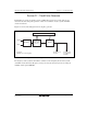


Section 22 Clock Pulse Generator
Page 1136 of 1384 R01UH0310EJ0500 Rev. 5.00
Sep 25, 2012
H8S/2426, H8S/2426R, H8S/2424 Group
Table 22.2 Crystal Resonator Characteristics
Frequency (MHz) 8 12 16 20
R
S
max (Ω) 80 60 50 40
C
0
max (pF) 7 7 7 7
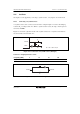
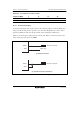
22.2.2 External Clock Input
An external clock signal can be input as shown in the examples in figure 22.4. If the XTAL pin is
left open, make sure that parasitic capacitance is no more than 10 pF. When the counter clock is
input to the XTAL pin, make sure that the external clock is held high in standby mode.
Table 22.3 shows the input conditions for the external clock. When an external clock is used, the
range of its frequencies is from 8 to 20 MHz.
EXTAL
XTAL
External clock input
Open state
(a) XTAL pin left open
EXTAL
XTAL
External clock input
(b) Counter clock input at XTAL pin
Figure 22.4 Connection of External Clock Input (Examples)