
Datasheet
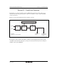


Section 22 Clock Pulse Generator
Page 1134 of 1384 R01UH0310EJ0500 Rev. 5.00
Sep 25, 2012
H8S/2426, H8S/2426R, H8S/2424 Group
22.1.2 PLL Control Register (PLLCR)
PLLCR sets the frequency multiplication factor used by the system-clock PLL circuit.
Care must be taken when writing to this register. For details, see section 22.3, System-Clock PLL
Circuit and Divider.
Bit Bit Name Initial Value R/W Description
7 to 4 ⎯ All 0 ⎯ Reserved
These bits are always read as 0 and cannot be
modified.
3 ⎯ 0 R/W Reserved
This bit can be read from or written to. However,
the write value should always be 0.
2 ⎯ 0 ⎯ Reserved
This bit is always read as 0 and cannot be
modified.
1
0
STC1
STC0
0
0
R/W
R/W
Frequency Multiplication Factor for System-
Clock PLL Circuit and System Clock Divider
Setting
The STC bits specify the frequency
multiplication factor and dividing ratio with
respect to the oscillator frequency.
00: × 1
01: × 2
10: Setting prohibited
11: 1/2