
Datasheet
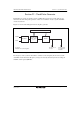


Section 22 Clock Pulse Generator
R01UH0310EJ0500 Rev. 5.00 Page 1133 of 1384
Sep 25, 2012
H8S/2426, H8S/2426R, H8S/2424 Group
Bit Bit Name Initial Value R/W Description
5 SDPSTP* 0 R/W SDRAMφ Output Disable
Controls SDRAMφ.
0: SDRMφ output.
1: Can be used as PH1/CS5/RAS5.
When the SDRAMφ output is selected, the pin
functions as follows in each power-down mode.
Normal operation: SDRAMφ output
Sleep mode: SDRAMφ output
Software standby mode: Fixed at a low level
Hardware standby mode: High-impedance state
All module clock stop mode: SDRAMφ output
4 ⎯ 0 ⎯ Reserved
This bit is always read as 0 and cannot be
modified.
3 STCS 0 R/W Frequency Multiplication Factor Switching Mode
Select
Selects the operation when the PLLCR register
setting is changed.
0: Specified multiplication factor is valid after
transition to software standby mode.
1: Specified multiplication factor is valid
immediately after STC1 and STC0 bits are
rewritten.
2
1
0
⎯
⎯
⎯
0
0
0
R/W
R/W
R/W
Reserved
These bits are always read as 0 and cannot be
modified.
Note: * The H8S/2426 group and H8S/2424 group do not have this bit. The pin always
functions as an I/O port regardless of this bit setting.