
Datasheet


Section 21 Flash Memory
R01UH0310EJ0500 Rev. 5.00 Page 1091 of 1384
Sep 25, 2012
H8S/2426, H8S/2426R, H8S/2424 Group
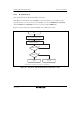
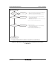
21.4.5 Block Erase
Write H'20xx in the first bus cycle and H'D0xx to the lowest address (an even address) of the
target block in the second cycle; automatic erasure (erasing data and verifying the erased status)
starts in the specified block.
Completion of automatic erasure can be checked through the FMRDY bit in FLMSTR.
The FMRDY bit is 0 (busy) during automatic erasure and becomes 1 (ready) when erasure is
completed.
After automatic erasure is completed, the result can be checked through the FMERSF bit in
FLMSTR (refer to section 21.6, Full Status Check).
Figure 21.4 shows a flowchart of the block erase command processing.
In the EW0 mode, the read status register mode is entered as soon as automatic erasure starts, and
the status register can be read. The SR7 bit in the status register becomes 0 when automatic
erasure starts and returns to 1 when erasure is completed. In this case, the flash memory stays in
the read status register mode until a read array command is issued. If an erase error occurs, repeat
a sequence of the clear status register command -> block erase command at least three times until
no erase error occurs.