
Datasheet

Section 19 Synchronous Serial Communication Unit (SSU)
Page 1072 of 1384 R01UH0310EJ0500 Rev. 5.00
Sep 25, 2012
H8S/2426, H8S/2426R, H8S/2424 Group
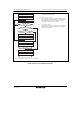
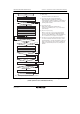
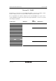
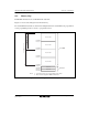
(4) Data Transmission/Reception
Figure 19.17 shows a flowchart example of simultaneous transmission/reception. The data
transmission/reception is performed combining the data transmission and data reception as
mentioned above. The data transmission/reception is started by writing transmit data to SSTDR
with TE = RE = 1.
Before switching transmission mode (TE = 1) or reception mode (RE = 1) to
transmission/reception mode (TE = RE = 1), clear the TE and RE bits to 0. When starting the
transfer, confirm that the TEND, RDRF, and ORER bits are cleared to 0 before setting the TE or
RE bits to 1.