
Datasheet


Section 19 Synchronous Serial Communication Unit (SSU)
Page 1068 of 1384 R01UH0310EJ0500 Rev. 5.00
Sep 25, 2012
H8S/2426, H8S/2426R, H8S/2424 Group
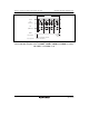
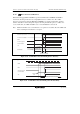
(2) Data Transmission
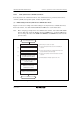
Figure 19.13 shows an example of transmission operation, and figure 19.14 shows a flowchart
example of data transmission. When transmitting data in clock synchronous communication mode,
the SSU operates as shown below.
In master mode, the SSU outputs a transfer clock and data. In slave mode, when a transfer clock is
input to the SSCK pin, the SSU outputs data in synchronization with the transfer clock.
Writing transmit data to SSTDR after the TE bit is set to 1 clears the TDRE bit in SSSR to 0, and
the SSTDR contents are transferred to SSTRSR. After that, the SSU sets the TDRE bit to 1 and
starts transmission. At this time, if the TIE bit in SSER is set to 1, a TXI interrupt is generated.
When 1-frame data has been transferred with TDRE = 0, the SSTDR contents are transferred to
SSTRSR to start the next frame transmission. When the 8th bit of transmit data has been
transferred with TDRE = 1, the TEND bit in SSSR is set to 1 and the state is retained. At this time,
if the TEIE bit is set to 1, a TEI interrupt is generated.
While the ORER bit in SSSR is set to 1, transmission is not performed. Check that the ORER bit
is cleared to 0.
LSI operation
User operation
SSO
SSCK
TDRE
TEND
Data written
to SSTDR
TXI interrupt
generated
TEI interrupt
generated
TXI interrupt
generated
Data written
to SSTDR
Bit 0 Bit 1 Bit 7 Bit 0 Bit 1 Bit 7
1 frame 1 frame
Figure 19.13 Example of Transmission Operation
(Clock Synchronous Communication Mode)