
Datasheet


Section 19 Synchronous Serial Communication Unit (SSU)
R01UH0310EJ0500 Rev. 5.00 Page 1053 of 1384
Sep 25, 2012
H8S/2426, H8S/2426R, H8S/2424 Group
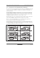
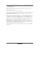
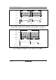
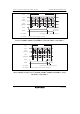
19.4.4 Communication Modes and Pin Functions
The SSU switches the input/output pin (SSI, SSO, SSCK, and SCS) functions according to the
communication modes and register settings. When a pin is used as an input pin, clear the
corresponding bit in each data direction register (DDR) to 0. The relationship of communication
modes and input/output pin functions are shown in tables 19.4 to 19.6.
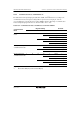
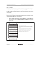
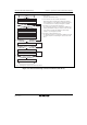
Table 19.4 Communication Modes and Pin States of SSI and SSO Pins
Register Setting Pin State
Communication
Mode
SSUMS BIDE MSS TE RE SSI SSO
0 0 0 0 1 ⎯ Input SSU communication
mode
1 0 Output ⎯
1 Output Input
1 0 1 Input ⎯
1 0 ⎯ Output
1 Input Output
0 1 0 0 1 ⎯ Input SSU (bidirectional)
communication mode
1 0 ⎯ Output
1 0 1 ⎯ Input
1 0 ⎯ Output
1 0 0 0 1 Input ⎯ Clock synchronous
communication mode
1 0 ⎯ Output
1 Input Output
1 0 1 Input ⎯
1 0 ⎯ Output
1 Input Output
[Legend]
⎯: Not used as SSU pin (can be used as I/O port)