
Datasheet


Section 19 Synchronous Serial Communication Unit (SSU)
Page 1052 of 1384 R01UH0310EJ0500 Rev. 5.00
Sep 25, 2012
H8S/2426, H8S/2426R, H8S/2424 Group
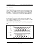
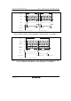
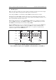
19.4.3 Relationship between Data Input/Output Pins and Shift Register
The connection between data input/output pins and the SS shift register (SSTRSR) depends on the
combination of the MSS and BIDE bits in SSCRH and the SSUMS bit in SSCRL. Figure 19.3
shows the relationship.
The SSU transmits serial data from the SSO pin and receives serial data from the SSI pin when
operating with BIDE = 0 and MSS = 1 (standard, master mode) (see figure 19.3 (1)). The SSU
transmits serial data from the SSI pin and receives serial data from the SSO pin when operating
with BIDE = 0 and MSS = 0 (standard, slave mode) (see figure 19.3 (2)).
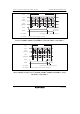
The SSU transmits and receives serial data from the SSO pin regardless of master or slave mode
when operating with BIDE = 1 (bidirectional mode) (see figures 19.3 (3) and (4)).
However, even if both the TE and RE bits are set to 1, transmission and reception are not
performed simultaneously. Either the TE or RE bit must be selected.
The SSU transmits serial data from the SSO pin and receives serial data from the SSI pin when
operating with SSUMS = 1. The SSCK pin outputs the internal clock when MSS = 1 and function
as an input pin when MSS = 0 (see figures 19.3 (5) and (6)).
SSCK
Shift register
(SSTRSR)
Shift register
(SSTRSR)
Shift register
(SSTRSR)
Shift register
(SSTRSR)
SSO
SSI
SSCK
SSO
SSI
SSCK
SSO
SSI
SSCK
SSO
SSI
(1) When SSUMS = 0, BIDE = 0 (standard mode),
MSS = 1, TE = 1, and RE = 1
SSCK
Shift register
(SSTRSR)
SSO
SSI
SSCK
Shift register
(SSTRSR)
SSO
SSI
(2) When SSUMS = 0, BIDE = 0 (standard mode),
MSS = 0, TE = 1, and RE = 1
(3) When SSUMS = 0, BIDE = 1 (bidirectional mode),
MSS = 0, and either TE or RE = 1
(4) When SSUMS = 0, BIDE = 1 (bidirectional mode),
MSS = 1, and either TE or RE = 1
(5) When SSUMS = 1 and MSS = 1
(6) When SSUMS = 1 and MSS = 0
Figure 19.3 Relationship between Data Input/Output Pins and the Shift Register