
Datasheet


Section 19 Synchronous Serial Communication Unit (SSU)
Page 1040 of 1384 R01UH0310EJ0500 Rev. 5.00
Sep 25, 2012
H8S/2426, H8S/2426R, H8S/2424 Group
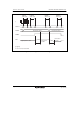
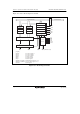
19.3.1 SS Control Register H (SSCRH)
SSCRH specifies master/slave device selection, bidirectional mode enable, SSO pin output value
selection, SSCK pin selection, and SCS pin selection.
Bit Bit Name
Initial
Value R/W Description
7 MSS 0 R/W Master/Slave Device Select
Selects that this module is used in master mode or
slave mode. When master mode is selected, transfer
clocks are output from the SSCK pin. When the CE bit
in SSSR is set, this bit is automatically cleared.
0: Slave mode is selected.
1: Master mode is selected.
6 BIDE 0 R/W Bidirectional Mode Enable
Selects that both serial data input pin and output pin
are used or one of them is used. However,
transmission and reception are not performed
simultaneously when bidirectional mode is selected.
For details, section 19.4.3, Relationship between Data
Input/Output Pins and Shift Register.
0: Standard mode (two pins are used for data input and
output)
1: Bidirectional mode (one pin is used for data input
and output)
5 ⎯ 0 R/W Reserved
This bit is always read as 0. The write value should
always be 0.