
Datasheet


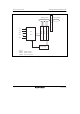

Section 18 D/A Converter
Page 1030 of 1384 R01UH0310EJ0500 Rev. 5.00
Sep 25, 2012
H8S/2426, H8S/2426R, H8S/2424 Group
18.3 Register Descriptions
The D/A converter has the following registers.
• D/A data register 2 (DADR2)
• D/A data register 3 (DADR3)
• D/A control register 23 (DACR23)
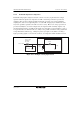
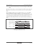
18.3.1 D/A Data Registers 2 and 3 (DADR2 and DADR3)
DADR2 and DADR3 are 8-bit readable/writable registers that store data for conversion.
Whenever analog output is enabled, the values in DADR are converted and output to the analog
output pins.
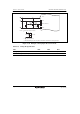
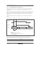
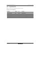
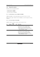
18.3.2 D/A Control Register 23 (DACR23)
DACR23 controls the operation of channels 2 and 3 in the D/A converter.
Bit Bit Name
Initial
Value R/W Description
7 DAOE3 0 R/W D/A Output Enable 3
Controls D/A conversion and analog output.
0: Channel 3 analog output (DA3) is disabled.
1: Channel 3 D/A conversion is enabled; channel 3
analog output (DA3) is enabled.
6 DAOE2 0 R/W D/A Output Enable 2
Controls D/A conversion and analog output.
0: Channel 2 analog output (DA2) is disabled.
1: Channel 2 D/A conversion is enabled; channel 2
analog output (DA2) is enabled.