
Datasheet


Section 2 CPU
Page 76 of 1384 R01UH0310EJ0500 Rev. 5.00
Sep 25, 2012
H8S/2426, H8S/2426R, H8S/2424 Group
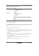
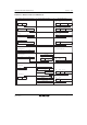
Table 2.12 Absolute Address Access Ranges
Absolute Address Normal Mode* Advanced Mode
Data address 8 bits (@aa:8) H'FF00 to H'FFFF H'FFFF00 to H'FFFFFF
16 bits (@aa:16) H'0000 to H'FFFF H'000000 to H'007FFF,
H'FF8000 to H'FFFFFF
32 bits (@aa:32) H'000000 to H'FFFFFF
Program instruction
address
24 bits (@aa:24)
Note: * Not available in this LSI.
2.7.6 Immediate—#xx:8/#xx:16/#xx:32
The instruction code contains 8-bit (#xx:8), 16-bit (#xx:16), or 32-bit (#xx:32) immediate data as
an operand.
The ADDS, SUBS, INC, and DEC instructions contain immediate data implicitly. Some bit
manipulation instructions contain 3-bit immediate data in the instruction code, specifying a bit
number. The TRAPA instruction contains 2-bit immediate data in its instruction code, specifying a
vector address.
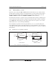
2.7.7 Program-Counter Relative—@(d:8, PC) or @(d:16, PC)
This mode is used in the Bcc and BSR instructions. An 8-bit or 16-bit displacement contained in
the instruction code is sign-extended and added to the 24-bit PC contents to generate a branch
address. Only the lower 24 bits of this branch address are valid; the upper 8 bits are all assumed to
be 0 (H'00). The PC value to which the displacement is added is the address of the first byte of the
next instruction, so the possible branching range is −126 to +128 bytes (–63 to +64 words) or
−32766 to +32768 bytes (−16383 to +16384 words) from the branch instruction. The resulting
value should be an even number.