
Datasheet


Section 17 A/D Converter
Page 1020 of 1384 R01UH0310EJ0500 Rev. 5.00
Sep 25, 2012
H8S/2426, H8S/2426R, H8S/2424 Group
17.7 Usage Notes
17.7.1 Module Stop Function Setting
Operation of the A/D converter can be disabled or enabled using the module stop control register.
The initial setting is for operation of the A/D converter to be halted. Register access is enabled by
clearing the module stop state. Set the CKS1 and CKS2 bits to 1 to set ADCLK to φ, and clear the
ADST, TRGS1, TRGS0, and EXTRGS bits all to 0 to disable A/D conversion when entering
module stop state after operation of the A/D converter. After that, set the module stop control
register after executing a dummy read by one word. For details, see section 23, Power-Down
Modes.
17.7.2 A/D Input Hold Function in Software Standby Mode
When this LSI enters software standby mode with A/D conversion enabled, the analog inputs are
retained, and the analog power supply current is equal to as during A/D conversion. If the analog
power supply current needs to be reduced in software standby mode, set the CKS1 and CKS2 bits
to 1 to set ADCLK to φ, and clear the ADST, TRGS1, TRGS0, and EXTRGS bits all to 0 to
disable A/D conversion. After that, enter software standby mode after executing a dummy read by
one word.
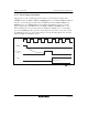
17.7.3 Restarting the A/D Converter
When the ADST bit has been cleared to 0, A/D converter stops in synchronization with the
ADCLK and then enters the standby sate. After the ADST bit has been cleared, the converter may
not actually make the transition to the standby state for up to 10 cycles (φ), so do not change the
channels of the ADCLK, motion mode, or analog input at this time.
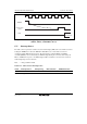
When restarting the A/D converter right after the ADST bit has been cleared to 0, read the 16
bytes from ADDRA to ADDRH and then start the A/D converter by setting the ADST bit to 1. If
the converter is in single mode or one-cycle scan mode, however, the ADST bit can be set to 1 by
clearing the ADF bit to 0 after confirming that the ADF bit had been set to 1 on completion of the
previous round of conversion.