
Datasheet


Section 17 A/D Converter
R01UH0310EJ0500 Rev. 5.00 Page 1017 of 1384
Sep 25, 2012
H8S/2426, H8S/2426R, H8S/2424 Group
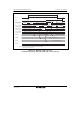
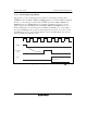
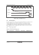
ADTRG0
ADST
A/D conversion
φ
Internal trigger
signal
Figure 17.8 External Trigger Input Timing when Multiple Units Start Simultaneously
(TRSG1, TRGS0, and EXTRGS = B'111)
17.5 Interrupt Source
The A/D converter generates an A/D conversion end interrupt (ADI) at the end of A/D conversion.
Setting the ADIE bit to 1 when the ADF bit in ADCSR is set to 1 after A/D conversion is
completed enables ADI interrupt requests. The data transfer controller (DTC)* and DMA
controller (DMAC) can be activated by an ADI interrupt. Having the converted data read by the
DTC* or DMAC in response to an ADI interrupt enables continuous conversion to be achieved
without imposing a load on software.
Note: * Only possible in unit 0.
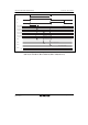
Table 17.8 A/D Converter Interrupt Source
Name Interrupt Source Interrupt Flag DTC Activation DMAC Activation
ADI0 A/D conversion end ADF Possible* Possible
Note: * Only possible in unit 0.