
Datasheet

Section 17 A/D Converter
R01UH0310EJ0500 Rev. 5.00 Page 997 of 1384
Sep 25, 2012
H8S/2426, H8S/2426R, H8S/2424 Group
17.3.1 A/D Data Registers A to H (ADDRA to ADDRH)
There are eight 16-bit read-only ADDR registers, ADDRA to ADDRH, used to store the results of
A/D conversion. The ADDR registers, which store a conversion result for each channel, are shown
in tables 17.3 and 17.4.
The converted 10-bit data is stored in bits 15 to 6. The lower 6-bit data is always read as 0.
The data bus between the CPU and the A/D converter has a 16-bit width. The data can be read
directly from the CPU. ADDR must not be accessed in 8-bit units and must be accessed in 16-bit
units.
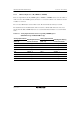
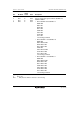
Table 17.3 Analog Input Channels and Corresponding ADDR Registers
(H8S/2426 Group and H8S/2426R Group)
Analog Input Channel Analog Input Channel
Channel Set 0
(CH3 = 0)
Data Register Storing
Conversion Result
Channel Set 0
(CH3 = 0)
Data Register Storing
Conversion Result
AN0 ADDRA_0 AN8 ADDRA_1
AN1 ADDRB_0 AN9 ADDRB_1
AN2 ADDRC_0 AN10 ADDRC_1
AN3 ADDRD_0 AN11 ADDRD_1
AN4 ADDRE_0 AN12 ADDRE_1
AN5 ADDRF_0 AN13 ADDRF_1
AN6 ADDRG_0 AN14 ADDRG_1
AN7 ADDRH_0 AN15 ADDRH_1