
Datasheet

Section 17 A/D Converter
R01UH0310EJ0500 Rev. 5.00 Page 991 of 1384
Sep 25, 2012
H8S/2426, H8S/2426R, H8S/2424 Group
Section 17 A/D Converter
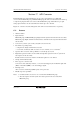
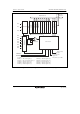
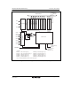
This LSI includes two units (units 0 and 1) of successive approximation type 10-bit A/D
converter. In the H8S/2426 group and H8S/2426R group, the A/D converter units 0 and 1 allow up
to eight analog input channels to be selected. In the H8S/2424 group, unit 0 allows up to eight
analog input channels to be selected while unit 1 allows up to two channels.
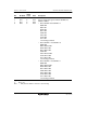
Figures 17.1 and 17.2 show block diagrams of the A/D converter units 0 and 1, respectively.
17.1 Features
• 10-bit resolution
• Input channels:
H8S/2426 group and H8S/2426R group: Eight channels (total of 16 channels for the two units)
H8S/2424 group: Eight channels for unit 0 and two channels for unit 1 (total of 10 channels for
the two units)
• Conversion cycle: 64 cycles or 40 cycles (A/D conversion clock)
• Two kinds of operating modes
⎯ Single mode: Single-channel A/D conversion
⎯ Scan mode: Continuous A/D conversion on 1 to 4 channels, or 1 to 8 channels*
1
• Separate A/D conversion clock specifiable for each unit (φ, φ/2, or φ/4)
• Eight data registers for A/D converter unit 0 and eight data registers for unit 1*
2
(total of 16
data registers for the two units)
Results of A/D conversion are held in a 16-bit data register for each channel.
• Sample and hold functionality
• Three types of conversion start
Conversion can be started by software, a conversion start trigger by the 16-bit timer pulse unit
(TPU) or 8-bit timer (TMR), or an external trigger signal.
• Interrupt source
A/D conversion end interrupt (ADI) request can be generated.
• Module stop state specifiable
Notes: 1. Continuous A/D conversion on 1 to 2 channels in the H8S/2424 group.
2. Two data registers for unit 1 (total of ten data registers for the two units) in the
H8S/2424 group.