
Datasheet

Section 16 I2C Bus Interface 2 (IIC2)
Page 990 of 1384 R01UH0310EJ0500 Rev. 5.00
Sep 25, 2012
H8S/2426, H8S/2426R, H8S/2424 Group
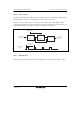
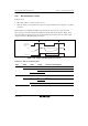
8. Notes on Changing from Master Transmit Mode to Master Receive Mode
If TRS is cleared to 0 before the falling edge of the 9th clock in master transmit mode when
master transmit mode is changed to master receive mode, this module outputs the receive clock
in synchronization with the internal clock whether ICDRR is read (dummy read) or not.
At that time, if ICDRR is read (dummy read) at or after the 9th receive clock pulse due to
DMAC transfer or DTC transfer, the output of the next receive clock is not triggered even if
ICDRR is read (dummy read). This module stops outputting the receive clock.
Then, the communication hangs up with SCL fixed low.
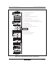
Ways to avoid this phenomenon are listed below.
(1) Design the timing so that ICDRR is read (dummy read) before the 9th receive clock pulse
when master transmit mode is changed to master receive mode.
(2) Clear TRS to 0 at or after the falling edge of the 9th transmit clock when master transmit
mode is changed to master receive mode.
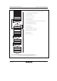
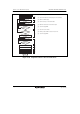
In way (2), before clearing TRS to 0 at or after the falling edge of the 9th transmit clock,
confirm the SCLO bit (SCL monitor flag) in ICCR2 has been set to 0 (the SCL pin outputs
low).
Also in way (2), reading ICDRR (dummy read) triggers the output of the first receive clock in
master receive mode. No problem occurs even if reading ICDRR (dummy read) is delayed due
to DMAC or DTC transfer or by interrupt processing. Steps (1) through (3) (no interrupts are
received during these steps) in figure 16.15, Sample Flowchart for Master Receive Mode, are
unnecessary.