
Datasheet


Section 2 CPU
Page 72 of 1384 R01UH0310EJ0500 Rev. 5.00
Sep 25, 2012
H8S/2426, H8S/2426R, H8S/2424 Group
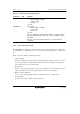
Table 2.10 Block Data Transfer Instructions
Instruction Size Function
EEPMOV.B
EEPMOV.W
⎯
⎯
if R4L ≠ 0 then
Repeat @ER5+ → @ER6+
R4L–1 → R4L
Until R4L = 0
else next;
if R4 ≠ 0 then
Repeat @ER5+ → @ER6+
R4–1 → R4
Until R4 = 0
else next;
Transfers a data block. Starting from the address set in ER5, transfers
data for the number of bytes set in R4L or R4 to the address location
set in ER6.
Execution of the next instruction begins as soon as the transfer is
completed.
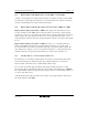
2.6.2 Basic Instruction Formats
The H8S/2600 Series instructions consist of 2-byte (1-word) units. An instruction consists of an
operation field (op), a register field (r), an effective address extension (EA), and a condition field
(cc).
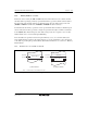
Figure 2.11 shows examples of instruction formats.
• Operation Field
Indicates the function of the instruction, the addressing mode, and the operation to be carried
out on the operand. The operation field always includes the first four bits of the instruction.
Some instructions have two operation fields.
• Register Field
Specifies a general register. Address registers are specified by 3 bits, data registers by 3 bits or
4 bits. Some instructions have two register fields. Some have no register field.
• Effective Address Extension
8, 16, or 32 bits specifying immediate data, an absolute address, or a displacement.
• Condition Field
Specifies the branching condition of Bcc instructions.