
Datasheet
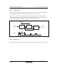

Section 16 I2C Bus Interface 2 (IIC2)
R01UH0310EJ0500 Rev. 5.00 Page 983 of 1384
Sep 25, 2012
H8S/2426, H8S/2426R, H8S/2424 Group
No
Yes
RDRF=1 ?
No
Yes
RDRF=1 ?
Last receive
- 1?
Mater receive mode
Clear TEND in ICSR
Set TRS = 0 (ICCRA)
Clear TDRE of ICSR
Set ACKBT = 0 (ICIER)
Dummy read ICDRR
Read RDRF in ICSR
Read ICDRR
Set ACKBT = 1 (ICIER)
Set RCVD = 1 (ICCRA)
Read ICDRR
Read RDRF in ICSR
Write BBSY = 0
and SCP = 0
Read STOP of ICSR
Read ICDRR
Set RCVD = 0 (ICCRA)
Set MST = 0 (ICCRA)
End
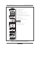
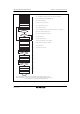
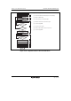
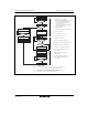
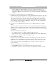
Note: * Ensure that no interrupts are received while steps [1] through [3] are being processed.
Additional information: If only one byte is received, steps [2] through [6] are omitted following step [1],
and processing jumps to step [7]. Step [8] is ICDDR dummy read.
No
Yes
STOP=1 ?
No
Yes
[1] Clear TEND, select master receive mode, and then clear TDRE.
*
[2] Set acknowledge to the transmitting device.
*
[3] Dummy read ICDDR.
*
[4] Wait for 1 byte to be received.
[5] Check if the (last receive - 1).
[6] Read the receive data.
[7] Set acknowledge of the final byte. Disable continuous receive (RCVD = 1).
[8] Read receive data of (final byte - 1).
[9] Wait for the final byte to be received.
[10] Clear STOP flag.
[11] Stop condition issuance.
[12] Wait for the generation of stop condition.
[13] Read the receive data of the final byte.
[14] Clear RCVD to 0.
[15] Set slave receive mode.
[1]
[2]
[3]
[4]
[5]
[6]
[7]
[8]
Clear STOP in ICSR
[10]
[9]
[11]
[12]
[13]
[14]
[15]
Figure 16.15 Sample Flowchart for Master Receive Mode