
Datasheet


Section 9 Data Transfer Controller (DTC)
R01UH0310EJ0500 Rev. 5.00 Page 483 of 1384
Sep 25, 2012
H8S/2426, H8S/2426R, H8S/2424 Group
9.3 Activation Sources
The DTC operates when activated by an interrupt or by a write to DTVECR or DTCCR by
software. An interrupt request can be directed to the CPU or DTC, as designated by the
corresponding DTCER bit. At the end of a data transfer (or the last consecutive transfer in the case
of chain transfer), the activation source or corresponding DTCER bit is cleared. The activation
source flag, in the case of RXI0, for example, is the RDRF flag of SCI_0.
When an interrupt has been designated a DTC activation source, existing CPU mask level and
interrupt controller priorities have no effect. If there is more than one activation source at the same
time, the DTC operates in accordance with the default priorities.
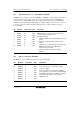
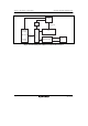
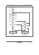
Table 9.1 shows a relationship between activation sources and DTCER clear conditions. Figure
9.2 shows a block diagram of activation source control. For details see section 5, Interrupt
Controller.
Table 9.1 Relationship between Activation Sources and DTCER Clearing
Activation Source
DISEL = 0 and Specified
Number of Transfers Has
Not Ended
DISEL = 1 or Specified Number
of Transfers Has Ended
Activation by software SWDTE bit is cleared to 0
• SWDTE bit remains set to 1
• Interrupt request to CPU
Activation by an interrupt
• Corresponding DTCER bit
remains set to 1.
• Activation source flag is
cleared to 0.
• Corresponding DTCER bit is
cleared to 0.
• Activation source flag remains
set to 1.
• Interrupt that became the
activation source is requested
to the CPU.